Donate to build this Ugly CNC...

Donate to build Ugly CNC ...

วันอังคารที่ 22 กุมภาพันธ์ พ.ศ. 2554

Test Board


At last I'm going to test board but I'm not quite sure it will work or not.
So,I decide to test it with LED first.I have a test board like below and use four small hold together at negative pole and at positive pole I pull it up with +5 vDC to limit the current.It's simple test circuit.


Then I connect all wire like below.It quite look mess.I use my simple rectifiier +5vDC and +12vDC to be the power source feed to my board.I've to aware and make sure for the 5v and 12v.Not to swap it.


It work !!! I'm so glad.

Let see video in below. The light from four LED can blink.


Seem there's a little problem for the green LED that not blink.So,I decide to change it to be the same colour.
Look good and seem to be ok for my step motor.The real use.


Yahoo, My step motor can be rotated according to my control.I take time to find the pattern from LED.
After try out and find the information from Mr.Google again and again.
Finally,I finish my board. 

See the video for the rotation of my step motor from controlling of my board.


Next time will be hardware part which I've no experience before to build CNC machine.

Let see how if I can do it ugly or not ....

วันพฤหัสบดีที่ 17 กุมภาพันธ์ พ.ศ. 2554

Control IC and leg board


I'm going to fill the control IC to my board.
Here's the picture of IC that I'll fill in to board.
I can get the detail.I mean datasheet of this IC from Mr.Google.

Very convenience.


Let see how I fill the control IC into my board. It quite easy.
At the end of this motion,I just press it to make sure it tight enough.


At the end of this board,I have to raise up my board a little bit so that if there's something touch the back board,It will not short circuit.

Here is some set of screw,I call it leg board.


I will not show movie of how to fill leg board into my board since it's very easy.

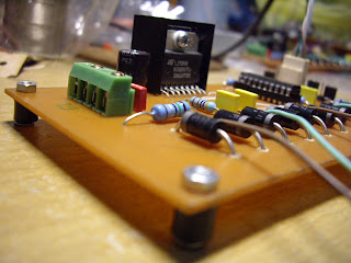
Let see some pictures of this contruction how it is ...


Next blog will be testing of my board.

Let see how its work.

วันอาทิตย์ที่ 13 กุมภาพันธ์ พ.ศ. 2554

White connector and wire

Now I'm ready to assemble the white connector.
Here is the set of my white connector.
There're some wire that have to use with this connector.


See the video below how I can do this white connector.


After finish the white connector,I twist the wire so that it will become single wire and not mess my board.


Here is my jumper in order to set some parameters for the control IC.


See the picture,It's quite ok.


Then I use some wire again to be the cable to my step motor.


Let see in below video how I can peel this wire.
Very easy.


Almost finish it.Just only fill the control IC.


I'm very new for CNC machine.
Let see how well I can make it !


วันเสาร์ที่ 12 กุมภาพันธ์ พ.ศ. 2554

Big capacitor and Power IC


Here is the capacitor that I use to be the filter for the power of this board.It quite a bit big.


The location in the board will near the power connector.


Ah Ha.. Look good.


Now,I continue with the driver IC.

See in below for the component of driver IC that I will assemble into board.


Here is video that do with the driver IC.It assemble with the heatsink.


Then I fill the finished driver IC to my board.


Now,It's quite complete.


I'm so exciting to test it.

วันอังคารที่ 8 กุมภาพันธ์ พ.ศ. 2554

Other connectors

Here now I continue with two types of connector.It's use for control connector and power connector.

For the white connector to connect for the control board.It will be used for the direction CW or CCW,Step,Sync and Ground.

For the green connector is used for power line feed into board.There're 5 Vdc and 12Vdc include the ground line.


Here after install both connector type.For the hole of power,Sure that I have to expand it again.

See in previous video blog how I did it.


Nearly finish my driver board.Just a few equipments.

Follow my next blog....


วันพฤหัสบดีที่ 3 กุมภาพันธ์ พ.ศ. 2554

Continue with Capacitor and Connectors

Here now we can continue with the capacitor.


There're some capacitor that I have to fill into board.


I'll skip video for the solder wire of capacitor.Here after I finish for capacitors.


After this there're some pins for select option that I have to fill.


But seem the hole for pins is not big enough so I have to expand these holes again.
I use the small motor to drill the resistor legs but change the bigger bit.
Let see in video that how I do the expansion the holes for connectors.


I need to separate some of these connectors because this is two legs per piece.
I use the cutter again to cut it off.The plastic that hold the pin is not strong enough.It's ok let see video below.


Let follow my blog to see how it's complete.


วันอังคารที่ 1 กุมภาพันธ์ พ.ศ. 2554

Fill the socket IC into board.

Here are some socket IC that I have to fill into board.Unfortunately I don't have 20 pins for the control IC.So,I reuse the old socket IC from other boards then cut some pin to have 20 pins.


After I fill into board. Quite ugly.... but sure my control IC can fill in to socket IC and I'm quite sure that It will work.


I make this board until now and I realize that there's not any hole to fix my board.
So,I drill four hole to my board.

See below.

วันจันทร์ที่ 31 มกราคม พ.ศ. 2554

Assemble the driver boards for resistors and diodes.

After I finished some of resistors,I have to fill the bigest resistor in the board which quite hard.But I got success to fill it into board see in below for my trying.


Here is the complete figure for the assembling resistors into driver board.


The next device is diode.

It's fast diode to switch current for step motor.


But the funny thing is I can not fill diode's leg into board which quite small than the other holes.

So,I decide to expand the hole with my big electrical drill.It's look bit crazy and it works without doubt.Let see how I expand diode's leg.


Finish filling all diode and look good.


Next step is sold the diode's leg.


Now,I have to join diode's leg with the PCB by solder wire again and cut the diode's leg.


It's look good right ...


Next step is the socket IC.


To be continue.


Protect myself from smoke of solder wire

Because I have to work with solder wire so,I have to protect myself from smoke of it.

I use the simple rectifier 7812 to drive a big fan. You can see from video below.


It might not be able to protect my nose 100 % but at least I don't want to breathe the solder wire directly.
If there're more budget,I'll buy the smoke sucker.


Here is my simple rectifire 7805 and 7812 for 5Vdc and 12Vdc.

วันเสาร์ที่ 29 มกราคม พ.ศ. 2554

Assemble the driver board.


Last week,I've prepared the other two driver boards.
Since I use only one circuit page,so I've to do wires first.

See figures in the right hand side.


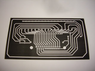
And here's the back of circuit board


Here is the technique to cut the small wire line.I use the cutter.Please be careful not to cut your finger.
Oterwise you'll have new wound.


After that,I continue this work with the resistances.


Here is the video that I've done for the solder resistance.


Let see tomorrow,What I can do more.

Changing the new coupling.

Finally,I can change the new coupling at the store that I bought several weeks ago.
Here is the cheap coupling.It's very very tired,After came from this changing.It's very far from my office to the store that I bought and there's a lot of traffic jam inside the city.This moment is very near chinese new year festival.However my objective is successful and the coupling is perfect suit with the screw 1/4".


I also bought more a step motor so that it will be the same type of motors.
Here is my three step motors.


Picture is quite good right,This is caused I've changed my camera from my mobile phone to real camera 10 Mpixels.

วันพุธที่ 26 มกราคม พ.ศ. 2554

Miss coupling ...


Several weeks ago,I bought two step motors and two couplings but seem that I bought the wrong size.It's hole is 1/4" which should enough for two sides of the rotor and other side is bigger than 1/4".

So,I think I'll go to change it.Hope that the store that I buy will compromise me to change.


Hole of the coupling is not equal.I want both side is equal to 1/4"
This is the cheap couplings.It's only 40 bth per each.
Let see I can change it or not ?

วันจันทร์ที่ 24 มกราคม พ.ศ. 2554

To create the driver for each motor.


I've the inspire heart to build this machine from a book step by step.
So,I would like to proof that it's possible or not.

Let see how's well I can do for the progress.

Because I've been doing it for several weeks but just think about it that Ho..
I can publish to other people to know what I do and how's the ugly CNC.
I can create from a CNC book.I've no experience before for this machine.
First thing I learn everything from Internet (Thanks!!!).
I've some electronics background from my University so it's not harder than my knowledge for the driver boards.

Here is my first driver board.


Last week I went to home.I've built more interface board and test with the existing step driver board to the computer.


and here is my designed draft in A4 paper.


It's work !! The motor can rotate as expect.
I've no time to record as the movie but I'll try in next week for more complete build.


Next week,I'll do more for the other two boards in figure below.


I've to do guild for the drill by cutter so that it will be more easy to pierce the board for leg of wire.


I plan to complete other two driver boards within next week.
Let see how the progress I can do more for the next week.