Donate to build this Ugly CNC...

Donate to build Ugly CNC ...

วันอังคารที่ 22 กุมภาพันธ์ พ.ศ. 2554

Test Board


At last I'm going to test board but I'm not quite sure it will work or not.
So,I decide to test it with LED first.I have a test board like below and use four small hold together at negative pole and at positive pole I pull it up with +5 vDC to limit the current.It's simple test circuit.


Then I connect all wire like below.It quite look mess.I use my simple rectifiier +5vDC and +12vDC to be the power source feed to my board.I've to aware and make sure for the 5v and 12v.Not to swap it.


It work !!! I'm so glad.

Let see video in below. The light from four LED can blink.


Seem there's a little problem for the green LED that not blink.So,I decide to change it to be the same colour.
Look good and seem to be ok for my step motor.The real use.


Yahoo, My step motor can be rotated according to my control.I take time to find the pattern from LED.
After try out and find the information from Mr.Google again and again.
Finally,I finish my board. 

See the video for the rotation of my step motor from controlling of my board.


Next time will be hardware part which I've no experience before to build CNC machine.

Let see how if I can do it ugly or not ....

วันพฤหัสบดีที่ 17 กุมภาพันธ์ พ.ศ. 2554

Control IC and leg board


I'm going to fill the control IC to my board.
Here's the picture of IC that I'll fill in to board.
I can get the detail.I mean datasheet of this IC from Mr.Google.

Very convenience.


Let see how I fill the control IC into my board. It quite easy.
At the end of this motion,I just press it to make sure it tight enough.


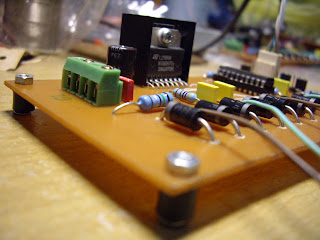
At the end of this board,I have to raise up my board a little bit so that if there's something touch the back board,It will not short circuit.

Here is some set of screw,I call it leg board.


I will not show movie of how to fill leg board into my board since it's very easy.

Let see some pictures of this contruction how it is ...


Next blog will be testing of my board.

Let see how its work.

วันอาทิตย์ที่ 13 กุมภาพันธ์ พ.ศ. 2554

White connector and wire

Now I'm ready to assemble the white connector.
Here is the set of my white connector.
There're some wire that have to use with this connector.


See the video below how I can do this white connector.


After finish the white connector,I twist the wire so that it will become single wire and not mess my board.


Here is my jumper in order to set some parameters for the control IC.


See the picture,It's quite ok.


Then I use some wire again to be the cable to my step motor.


Let see in below video how I can peel this wire.
Very easy.


Almost finish it.Just only fill the control IC.


I'm very new for CNC machine.
Let see how well I can make it !


วันเสาร์ที่ 12 กุมภาพันธ์ พ.ศ. 2554

Big capacitor and Power IC


Here is the capacitor that I use to be the filter for the power of this board.It quite a bit big.


The location in the board will near the power connector.


Ah Ha.. Look good.


Now,I continue with the driver IC.

See in below for the component of driver IC that I will assemble into board.


Here is video that do with the driver IC.It assemble with the heatsink.


Then I fill the finished driver IC to my board.


Now,It's quite complete.


I'm so exciting to test it.

วันอังคารที่ 8 กุมภาพันธ์ พ.ศ. 2554

Other connectors

Here now I continue with two types of connector.It's use for control connector and power connector.

For the white connector to connect for the control board.It will be used for the direction CW or CCW,Step,Sync and Ground.

For the green connector is used for power line feed into board.There're 5 Vdc and 12Vdc include the ground line.


Here after install both connector type.For the hole of power,Sure that I have to expand it again.

See in previous video blog how I did it.


Nearly finish my driver board.Just a few equipments.

Follow my next blog....


วันพฤหัสบดีที่ 3 กุมภาพันธ์ พ.ศ. 2554

Continue with Capacitor and Connectors

Here now we can continue with the capacitor.


There're some capacitor that I have to fill into board.


I'll skip video for the solder wire of capacitor.Here after I finish for capacitors.


After this there're some pins for select option that I have to fill.


But seem the hole for pins is not big enough so I have to expand these holes again.
I use the small motor to drill the resistor legs but change the bigger bit.
Let see in video that how I do the expansion the holes for connectors.


I need to separate some of these connectors because this is two legs per piece.
I use the cutter again to cut it off.The plastic that hold the pin is not strong enough.It's ok let see video below.


Let follow my blog to see how it's complete.


วันอังคารที่ 1 กุมภาพันธ์ พ.ศ. 2554

Fill the socket IC into board.

Here are some socket IC that I have to fill into board.Unfortunately I don't have 20 pins for the control IC.So,I reuse the old socket IC from other boards then cut some pin to have 20 pins.


After I fill into board. Quite ugly.... but sure my control IC can fill in to socket IC and I'm quite sure that It will work.


I make this board until now and I realize that there's not any hole to fix my board.
So,I drill four hole to my board.

See below.